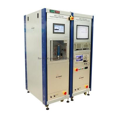
Combination Wave Test System Impulse Current Voltage Test Set
HV Hipot Electric Co., Ltd.- Input power:AC220V,22kV,3kVA, 60Hz
- Charging time:22kV completed within 40s~60s
- Residual voltage level:less or equal to 2.5kV
- Phase angle:0-360 degree, adjustable
- Output impedance:2ohm+,-10%
- Cabinet dimension:600(L) * 800(W) * 1800(H)mm
Base Info
- Model NO.:GDCL-20kV,10kA
- Test object cabinet:400(L) * 400(W) * 300(H)mm
- Weight:650kg
- Transport Package:Wooden Case
- Specification:SGS, ISO
- Trademark:HVHIPOT
- Origin:Wuhan, China
- HS Code:9030339000
- Production Capacity:500PCS,Year
Description
Basic Info.
Model NO. GDCL-20kV/10kA Test object cabinet 400(L) * 400(W) * 300(H)mm Weight 650kg Transport Package Wooden Case Specification SGS, ISO Trademark HVHIPOT Origin Wuhan, China HS Code 9030339000 Production Capacity 500PCS/YearProduct Description
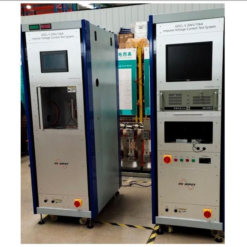
GDCL-20kV/10kA Impulse Combination Wave Test System/Impulse Voltage Current Test SystemI. Application
The equipment is according to combination wave testing requirement of the low-voltage power distribution system SPD II product, enable to generate impulse voltage (1.2/50μs) and impulse current (8/20μs), is used for grade III test and limiting voltage test of SPD and components. It is also used for impulse current test and residual voltage test of the MOV valve plate, unit and surge protective device(SPD), or used in other scientific research experiments.
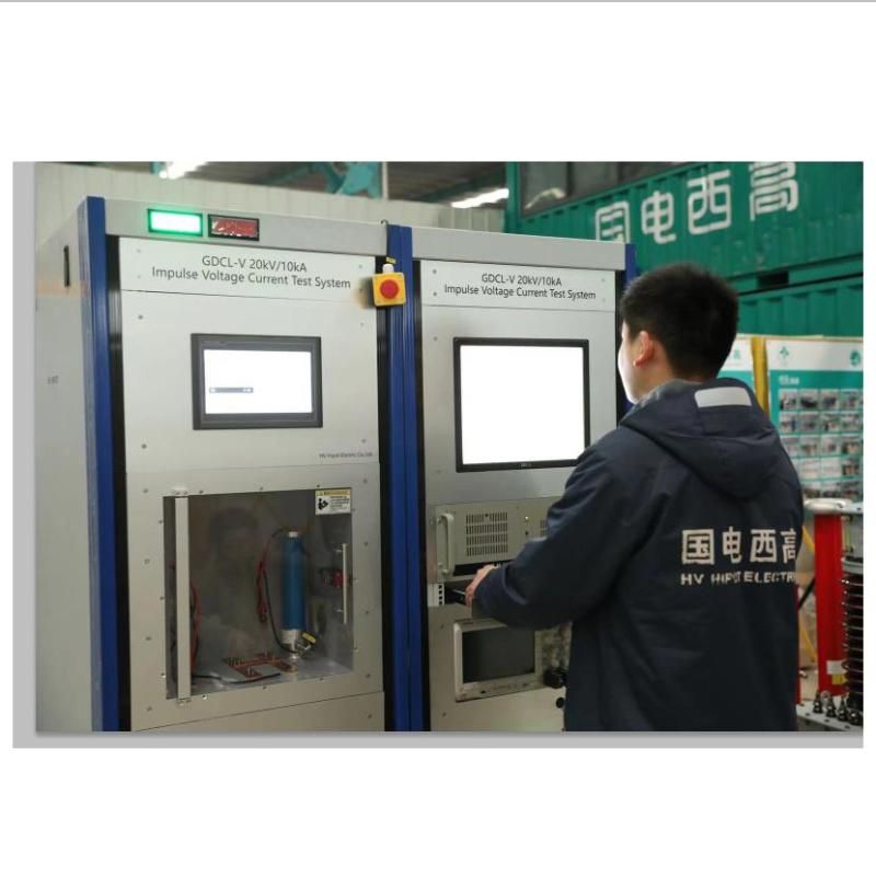
The device uses touch screen and PLC control technology, and the main performance meets the needs of domestic and foreign SPD products and their components for various combination wave testing.
II. Standards
- GB 18802.1-2012 GB 18802.1-2012 Surge protective devices connected to low-voltage power distribution systems Part 1:Requirements and test method
- GB/T 18802.12-2006 Surge protective devices connected to low-voltage power distribution systems Part 12: Guidelines for selection and use
- GB/T 16927.1-1997 High voltage test techniques Part 1: General test requirements
- GB/T 16927.2-1997 High voltage test techniques Part 2: Measuring systems
- GB/T 17626.5-1999 Electromagnetic compatibility-Testing and measurement techniques-Surge immunity test
- IEC61000-4-5 Electromagnetic compatibility (EMC) Part 4-5: Testing and measurement techniques - Surge immunity test
- IEC61643.11: Low-voltage surge protective devices Part 11: Surge protective devices connected to low-voltage power systems-Requirements and test methods
- IEC61643-21: Low voltage surge protective devices (SPD) Part 21: Surge protective devices connected to telecommunications and signalling networks-Performance requirements and testing methods
III. Applicable Conditions
- Altitude: 1000M;
- Ambient temperature: -5ºC~+40ºC, maximum daily temperature difference: 25ºC;
- Relative humidity: 85% (20ºC) without condensation;
- Service environment: Indoor;
- No conductive dust, no fire and explosion hazards, no corrosive metal and insulating Gases;
- The waveform of the power supply voltage is sine wave, the waveform distortion rate < 5%, and the voltage fluctuation <10%;
- Grounding resistance: ≤0.5Ω;
VI. Technical Specifications
The main technical parameters of the test platform are:
- Input power: AC220V/22kV/3kVA, 60Hz;
- Max. DC charging voltage: DC12kV, max. charging current 0.5A;
- Charging time: 22kV completed within 40s~60s;
- Charging voltage setting: Test initialization, pre-setting and adjusting of charging voltage;
- Residual voltage level: ≤2.5kV;
- Automatic polarity conversion: the number of positive and negative polarity impulse can be set separately;
- Phase angle: 0-360° adjustable;
- Impulse current generating circuit
Capacitance: 16uF, charging voltage: 12kV;
Output capacity: 10%~100%, anti-peak <20% (do not connect the decoupling load);
Output impedance: 0.5Ω (10kV/20kA);
- Combination wave generating circuit
Lightning voltage 1.2/50μs, lightning voltage rated amplitude: 2-20kV.
Capacitance: 8uF, charging voltage 22kV.
Output capacity: 10%~100%, anti-peak <20% (do not connect the decoupling load).
Output impedance: 2ohm ± 10%.
- Cabinet dimension: 600(L) * 800(W) * 1800(H)mm
- Test object cabinet: 400(L) * 400(W) * 300(H)mm
- Weight: about 650kg
- The cabinet is equipped with movable casters and fixed supports, which can be easily moved and positioned;
The device is equipped with a Lenovo all-in-one computer, placed next to the device, and the communication line is connected to the computer for waveform analysis.
VI. Main Component Performance
6.1 Impulse Capacitor
Impulse capacitance: 16uF*2/12kV;
Capacitor actual operation up to 22kV;
Quantity: 1 set;
6.2 Wave Modulation Unit
The wave modulation components of each working mode are integrated on an insulating board for easy disassembly, replacement and maintenance.
Different working modes can be easily switched, and detected by photoelectric sensor, automatically recognize the inserted waveform, and display it on the touch screen.
6.3 Data Acquisition Terminal
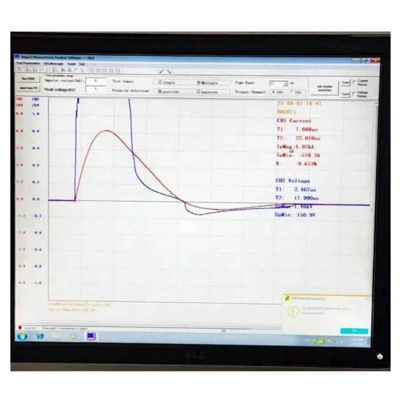
Use the MDO3012 oscilloscope (or other models provided by the customer) produced by Tektronix, the sampling frequency of 100MHz, 10k storage length, and 8bit vertical resolution. It can communicate with the computer via Ethernet. The data is analyzed and processed by the PC, and automatically measured and analyzed. Software can store waveforms and data in real time.
6.4 Control Unit
The touch screen and Mitsubishi PLC form a secondary control system with simple structure, convenient operation and easy maintenance. The control interface adopts professional software man-machine interface, which is friendly and easy to operate. Using 10-inch touch screen, friendly interface, easy to operate and expand.
6.5 Measurement Device
a) The device voltage measuring device uses a high voltage probe (RP1300H 300MHz 2.5kV) and a voltage divider. The high voltage probe can meet the residual voltage measurement below 2.5kV. Better meet customer's testing requirements for low residual voltage of signal products. The voltage divider is used for residual voltage requirements above 2.5kV.
- Probe parameters:
Input impedance: 100MΩ;
Maximum input voltage: 2.5kV (pulse);
Accuracy: 1%;
- Divider parameters:
Suitable for: 1.2/50 waveform;
b) The device current measuring device can be used to measure the suspended potential by using the core-through type Rogowski coil.
- Coil parameters:
Current measurement range: 0.5-15kA;
Output maximum voltage: 300V;
Split-flow ratio: 0.02V/A;
VII. Equipment safety and interlocking device
- The high voltage part of the equipment is isolated and grounded;
- The control cabinet is grounded, and one end of the test circuit is always grounded.
- The red high-voltage indicator light indicates that the high voltage is working, and the green high-voltage indicator light indicates that there is no high-voltage danger;
- When the test area protection door or emergency switch is opened, the high voltage is discharged to the ground, the equipment does not work, and the interlock indicator light is turned on;
- The main circuit of the equipment has a fuse wire for overcurrent protection to ensure safety;
- The entire set of equipment is pasted with a safety sign;
- The test can be stopped/pressed by the emergency stop button, and the internal high-voltage components and the output short-circuit ground can be realized;
- Equipped with a manual grounding rod for the cabinet maintenance;
- The equipment is equipped with an Omron electromagnetic lock switch on the test product door, and it is not allowed to open the test product door during the test to better ensure personal safety;
| Name | Model | Qty. |
| Software CD | 1 | |
| Fuse | 3A 10*38 | 1 |
| Power supply | 35W-24V | 1 |
| High voltage diode | 50kV 0.5A | 2 |
| Low inductance resistor | 1 Ω/100W | 4 |
| BNC Coaxial cable plug | 75-5 f9 | 1 |
IX. Equipment List
| No. | Name | Model/Specification | Qty. | Remark |
| 1 | Combination wave generator | GDCL-V 20kV/10kA | 1 | 20kV/10kA |
| 2 | Measurement system | GDCL-V 20kV/10kA | 1 | Without control cabinet |
| 3 | Waveform 1 | 8/20μs | 1 | |
| 4 | Waveform 2 | 1.2/50 8/20 | 1 | |
| 5 | Earthing rod | JDB5 | 1 | |
| 7 | Documents | Manual, test report and electrical drawings | 1 | |
| 8 | Operation load power supply | 0-500VAC | 1 | |
| 9 | Coupling mode | 9Uf*2 | 2 |